
Electrical Safety Solutions for Healthcare Facilities
Hospitals cannot afford unplanned loss of power. Engineered electrical safety solutions help healthcare facilities keep critical care operations running through a ground fault, protect reliability of emergency backup systems, and reduce the cost of unplanned repairs.
What Happens When a Ground Fault Reaches a Hospital’s Emergency Power System?
In a typical hospital, there is a 600V normal power system and a 600V generator power system. The most critical loads, including the emergency department and the intensive care unit, are fed from the emergency power distribution downstream of one or more transfer switches, which draw power from both systems.
Consider a ground fault occurring in a switchboard downstream of a transfer switch.
| Solidly grounded | High-resistance grounded | |
|---|---|---|
| Step 1The first fault occurs | A large current flow vaporizes components inside the switchboard and coats the inside of it with semi-conductive residue. | The same ground fault produces an alarm instead. There is no power interruption. |
| Step 2Upstream equipment responds | The high fault current stresses the upstream transformer and trips the upstream breaker, cutting all power to the critical loads. The transfer switch senses the loss, starts the emergency generator, and transfers the critical load over to it. | The main transformer is never subjected to the stresses of a fault, and the generator does not start and is not exposed to a fault current. |
| Step 3A second fault follows | Because the switchboard is now contaminated with residue from the first fault, a second fault often follows, damaging the switchboard further, stressing the generator with a high magnitude fault current, and tripping the generator breaker too. | The first fault is located and corrected before a second one can develop. |
| Step 4Impact on patient care | The critical loads, including the emergency department and the ICU, shut down and stay down. The hospital is forced into emergency mode and has to transfer critical patients to other areas not designed for their care, and in some cases to another hospital entirely. | Critical care operations continue uninterrupted throughout. |
| Step 5Getting back to normal | Feeders must be cut away from the failed switchboard, spliced, and extended to another power source, a process that takes many hours and leaves the critical loads on normal power only. Full restoration requires replacing the switchboard, which takes many months, since switchgear is built to order. | The damage is minimal, typically requiring the replacement of a single insulator, which can be scheduled when the hospital can accommodate a short, planned shutdown. |
|
Solidly grounded
|
High-resistance grounded
|
|
|---|---|---|
|
Step 1 |
A large current flow vaporizes components inside the switchboard and coats the inside of it with semi-conductive residue. |
The same ground fault produces an alarm instead. There is no power interruption. |
|
Step 2 |
The high fault current stresses the upstream transformer and trips the upstream breaker, cutting all power to the critical loads. The transfer switch senses the loss, starts the emergency generator, and transfers the critical load over to it. |
The main transformer is never subjected to the stresses of a fault, and the generator does not start and is not exposed to a fault current. |
|
Step 3 |
Because the switchboard is now contaminated with residue from the first fault, a second fault often follows, damaging the switchboard further, stressing the generator with a high magnitude fault current, and tripping the generator breaker too. |
The first fault is located and corrected before a second one can develop. |
|
Step 4 |
The critical loads, including the emergency department and the ICU, shut down and stay down. The hospital is forced into emergency mode and has to transfer critical patients to other areas not designed for their care, and in some cases to another hospital entirely. |
Critical care operations continue uninterrupted throughout. |
|
Step 5 |
Feeders must be cut away from the failed switchboard, spliced, and extended to another power source, a process that takes many hours and leaves the critical loads on normal power only. Full restoration requires replacing the switchboard, which takes many months, since switchgear is built to order. |
The damage is minimal, typically requiring the replacement of a single insulator, which can be scheduled when the hospital can accommodate a short, planned shutdown. |
The fault is the same in both columns. What differs is how much current the system makes available to it, and every consequence below the first step follows from that one design decision.
The Scale of the Problem
The U.S. Department of Labor’s Bureau of Labor Statistics compiled a Census of Occupational Injuries covering 1992 through 1998 showing that 2,287 workers died and 32,807 workers sustained days away from work due to electrical shock or electrical burn injuries. While the numbers have been gradually decreasing over the years, the problem still remains. Electrical hazards continue to account for roughly 5% to 6% of all workplace fatalities, with hundreds of non-fatal injuries requiring days away from work recorded every year, according to BLS data and the Electrical Safety Foundation International’s Workplace Injury and Fatality Statistics dashboard.
According to CapSchell Inc., a Chicago-based research and consulting firm specializing in preventing workplace injuries and deaths, there are an estimated five to ten arc flash explosions in electric equipment every day in the United States that result in hospitalization of workers.
Source: U.S. Bureau of Labor Statistics, Census of Fatal Occupational Injuries; Electrical Safety Foundation International, Workplace Injury and Fatality Statistics Report, March 5, 2026, citing OSHA 170 Form data 2011–2024; CapSchell Inc. estimate pending confirmation.
Electrical Challenges in Healthcare Facilities
Continuous Critical Care Operations
Operating rooms, ICUs, and emergency departments cannot tolerate an unplanned loss of power, and a single failed switchboard can force patient transfers to areas of the hospital not designed for their care.
Emergency Power System Reliability
Backup generators have to work the moment they’re called on. A fault that stresses a generator with high fault current before it’s ever needed threatens the exact backup power the hospital is depending on.
Personnel Safety
Facilities and biomedical engineering staff need to confirm equipment is de-energized before opening an enclosure, without exposing themselves to live parts in the process.
Cost of Unplanned Repairs
A fault that damages a switchboard can mean replacing it entirely, and switchgears built to order can take months to arrive, compared to single insulator replacements scheduled at the hospital’s convenience.
Supporting Compliance and Best Practices
Healthcare facility electrical systems are commonly designed and maintained with reference to the following:
Always consult applicable standards and project requirements when designing electrical systems.
High-Resistance Grounding for Hospital Power Systems
High-resistance grounding has been used in healthcare for many years and is considered best practice for hospitals. It is well known and recognized by the Canadian Electrical Code, and it is driven by four basic factors: power is not interrupted in the event of a single ground fault, damage at the point of fault is negligible, and the risk of a single ground fault escalating into a damaging line-to-line or three-phase fault is negligible.
It is best practice to equip both the low voltage (600V) and high voltage (4,160V) systems in a hospital with high-resistance grounding, typically in the form of a neutral grounding resistor applied between the transformer neutral and ground.
What this actually prevents
For systems up to 4,160V, where the resistor let-through current is 10A or less, an arc blast is unlikely, and the system can continue to operate with one ground fault present. Since the fault does not escalate, the distribution system stays safer and accidents causing a line-to-ground fault will not produce a hazardous blast or arc flash. Fault damage at the point of the fault is very low and easily repaired, which minimizes maintenance costs. Motor and generator laminations do not get burnt, and winding repair costs stay small.

Choosing the Right Level of Protection
| Tier | Product | Type of Protection |
|---|---|---|
| Pulsing | Sleuth | A self-contained HRG system with an integral pulsing circuit built in, to help locate a fault without a separate handheld setup. |
| Pulsing plus monitoring | Sleuth-M | Everything in Sleuth, plus an integral monitoring relay that continuously monitors the integrity of the grounding circuit itself. |
| Fail-safe | Gemini | A fail-safe HRG system with a redundant resistor path and a full-time monitoring relay, so a single resistor path failure does not mean losing ground fault protection. |
| Fail-safe plus pulsing | Gemini-PS | Everything in Gemini, plus integral pulsing for fault location. |
| Smart | Sentinel (built on the DSP-OHMNI relay) | Advanced HRG that protects up to 50 feeders, with critical process protection that keeps the system running even under a second ground fault. |
| Smart plus monitoring | Sentinel-M | Everything in Sentinel, plus an integral relay that continuously monitors the integrity of the grounding circuit. |
| Total system protection | Citadel | Combines Sentinel’s DSP-OHMNI relay, arc detection module, and isolation switch with Gemini’s twin resistance paths, so there is no single point of failure on either the resistor side or the arc detection side. The same second-fault protection and arc detection hold even during a resistor-side repair, so nothing about fault location or arc detection has to pause. The system to specify when downtime on repair is as unacceptable as the arc flash risk itself. |
table 2 version
|
Tier
|
Product
|
Type of Protection
|
|---|---|---|
|
Pulsing |
Sleuth |
A self-contained HRG system with an integral pulsing circuit built in, to help locate a fault without a separate handheld setup. |
|
Pulsing plus monitoring |
Sleuth-M |
Everything in Sleuth, plus an integral monitoring relay that continuously monitors the integrity of the grounding circuit itself. |
|
Fail-safe |
Gemini |
A fail-safe HRG system with a redundant resistor path and a full-time monitoring relay, so a single resistor path failure does not mean losing ground fault protection. |
|
Fail-safe plus pulsing |
Gemini-PS |
Everything in Gemini, plus integral pulsing for fault location. |
|
Smart |
Sentinel (built on the DSP-OHMNI relay) |
Advanced HRG that protects up to 50 feeders, with critical process protection that keeps the system running even under a second ground fault. |
|
Smart plus monitoring |
Sentinel-M |
Everything in Sentinel, plus an integral relay that continuously monitors the integrity of the grounding circuit. |
|
Total system protection |
Citadel |
Combines Sentinel’s DSP-OHMNI relay, arc detection module, and isolation switch with Gemini’s twin resistance paths, so there is no single point of failure on either the resistor side or the arc detection side. The same second-fault protection and arc detection hold even during a resistor-side repair, so nothing about fault location or arc detection has to pause. The system to specify when downtime on repair is as unacceptable as the arc flash risk itself. |
Reducing Incident Energy in the Event an Arc Flash Occurs
High-resistance grounding addresses the probability of an arc flash. A separate set of relays addresses what happens if one still occurs, and the difference in reaction time is dramatic: I-Gard’s arc detection relays detect the light signature of an arc in less than one millisecond and send an interruption signal, compared to roughly 300 milliseconds for a person to blink.
Voltage and current are already fixed properties of a given system. Duration is the one variable that can actually be controlled, and it matters more than intuition suggests, because the energy released does not grow at a steady rate. It’s estimated that there are five to ten arc flash explosions in electric equipment every day in the U.S. that require hospital treatment for the affected workers, and the difference between a survivable event and a severe one often comes down to milliseconds.
| Total Clearing Time | What Happens | Incident Energy |
|---|---|---|
| 35 ms | No significant damage to persons or switchgear, which can often be returned to service after checking insulation resistance. | 1.27 cal/cm² |
| 100 ms | Small damage, requiring cleaning and possibly some minor repair. | 3.23 cal/cm² |
| 500 ms | Large damage to both persons and the switchgear, which must be partly replaced. | 18.1 cal/cm² |
table 2 version
|
Total Clearing Time
|
What Happens
|
Incident Energy
|
|---|---|---|
|
35 ms |
No significant damage to persons or switchgear, which can often be returned to service after checking insulation resistance. |
1.27 cal/cm² |
|
100 ms |
Small damage, requiring cleaning and possibly some minor repair. |
3.23 cal/cm² |
|
500 ms |
Large damage to both persons and the switchgear, which must be partly replaced. |
18.1 cal/cm² |
That is roughly a fourteen-fold increase in incident energy between clearing a fault in 35 milliseconds and clearing it in 500, for the same underlying fault. The arc burning time is simply the time to detect the arc in addition to the time it takes to open the correct breaker. Reducing either event directly reduces how much energy ultimately gets released.
Protecting the People Working on the System
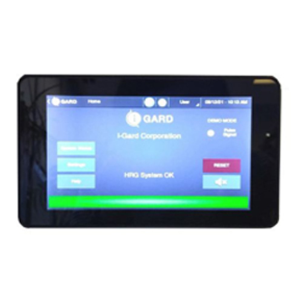
High-Resistance Grounding Systems (HRG)
Limits ground fault current to a level low enough that an arc blast is unlikely, so a single ground fault does not escalate into an arc flash. See the section above for the full explanation of how this works.
Low voltage (600V) and high voltage (4,160V) hospital distribution systems, including main electrical distribution and emergency generators.
Primary Benefit: Negligible arc flash hazard on a single ground fault, keeping the people working on or near the system out of the hazard in the first place, not just better protected once it starts.
Arc Flash Relays
Detect the light signature of an arc and trip a breaker fast enough to cut the incident energy released. See the section above for how clearing time and incident energy relate.
Switchgear and circuits where a facility needs to reduce incident energy on top of whatever ground fault protection is already in place.
Primary Benefit: Reduces the incident energy of an arc flash that is already in progress. This is the mitigate half of the prevent-and-mitigate pair, with high-resistance grounding covering the prevent half.
i-AVT (Absence of Voltage Tester)
Automates the voltage verification process, giving a positive, color-coded indication of the presence of voltage from 3V to 600V, absence of voltage, ground fault, and loss of phase. It’s panel-mounted rather than handheld, and powered from the source it monitors, with no external power supply required.
Panels and enclosures where NFPA 70E requires verification of an electrically safe work condition before work begins.
Primary Benefit: Meets the requirement for a permanently mounted test device under NFPA 70E-2018 Article 120.5 and OSHA 1910.147(d)(6), and gives a positive light-on indication of de-energization rather than the less reliable light-off indication most hand-held methods rely on.
Why Engineering Controls Come Before PPE
Reducing electrical hazards means reducing both the risk and the hazard. The hierarchy of hazard control measures, defined in ANSI Z10, ranks the available options from most to least effective.
Eliminating the hazard during design is the most effective control and should always be considered first, for example de-energizing equipment before work begins or installing high-resistance grounding, which reduces the frequency of arc flash incidents in the first place. Where elimination isn’t possible, the alternative options include substituting a less hazardous approach, redesigning the equipment, isolating the hazard (using engineering controls such as a relay with Zone Selective Interlocking or optical arc detection), establishing safe work practices, and only then relying on personal protective equipment.
Administrative controls and personal protective equipment sit at the bottom of that list for a reason as they should never be relied on as the primary means of controlling risk. PPE in particular, should be treated as the last line of defence for protection when the exposure risk can’t be minimized any other way. High-resistance grounding, arc detection relays, and absence of voltage testing are all engineering controls, sitting at the top of the hierarchy as the most effective form of protection.
Risk
How likely an event is to occur
Hazard
How severe it would be if the event did occur
Most effective at the top. I-Gard solutions sit in the two marked bands, not at the PPE end.
Why Healthcare Facilities Choose I-Gard
I-Gard is one of the only electrical safety technology companies whose product portfolio includes neutral grounding resistors, high-resistance grounding systems, and optical arc mitigation together. Our technology and expertise is aimed at reducing both the frequency of electrical hazards and their impact in the event they occur to protect personnel and equipment.
I-Gard was the first power resistor company in North America to be ISO 9001 certified, and is the only resistor manufacturer with a CSA-approved testing facility in-house, as well as the only resistor manufacturer with UL listing across its complete NGR product offering. I-Gard has also been approved by the Government of Canada under its Controlled Goods Program for Department of Defense applications.
For more than 40 years, customers have relied on I-Gard for the quality and robustness of its products, focus on customer service, and technical leadership, including active participation in IEEE community programs on technical and electrical safety standards, partnerships with universities to uncover new technologies, and the EFC scholarship program supporting electrical safety education.
From specification support and system design through training and commissioning, I-Gard stand behind every solution it provides.
Build a More Reliable Healthcare Electrical Infrastructure
Whether you’re protecting a critical care unit, adding second-fault protection to your main distribution system, or improving the reliability of your emergency generators, I-Gard can help identify the right electrical safety solution for your facility.