
High Resistance Grounding
When an Arc Flash Starts as
an Undetected Ground Fault
A phase-to-ground fault can remain below a relay’s pickup setting, undetected, while degrading insulation until it escalates into an arc flash. By then, the event may be far more severe than the original fault ever suggested, and potentially outside what the incident-energy study accounted for. Yet most facilities still solidly ground their low-voltage systems. That has been the default for decades. We think it deserves a much harder look.
Understanding the hazard before it escalates
What Is a Ground Fault, and Why Does It Matter So Much?
A ground fault is an unintended electrical connection between an energized conductor and ground. It can result from ordinary conditions such as loose connections, damaged insulation, moisture, or contamination. Once a ground fault occurs, the available fault current largely determines how severe the event can become. If the current is high enough, the fault can sustain an electrical arc through the air. The resulting heat, light, and pressure can produce an arc flash. The fault mechanism itself does not change whether the available current is a few hundred amps or only a few amps. What changes is the energy available to sustain it. The more current available to the fault, the more energy the system can release when an arc develops.
Ground faults matter because they are the most common type of fault in industrial power systems. According to the Industrial Power System Grounding Design Handbook, approximately 95% of faults are single-phase-to-ground faults. About 4% begin as phase-to-phase faults and 1% as three-phase faults. In other words, ground faults are not an unusual precursor to an electrical event. They are the predominant fault condition.
On a solidly grounded system, a phase-to-ground fault can produce significant arc-flash, thermal, and blast energy on its own. It also provides a credible path toward escalation into a phase-to-phase or three-phase arcing fault, particularly at 480 V and 600 V, which are common industrial system voltages. The more useful engineering question, then, is not simply how to protect personnel after an arc flash occurs. It is where the hazard can be addressed before a ground fault has the opportunity to escalate.
Arc-flash PPE is an essential layer of protection, but it is designed to reduce injury after an arc flash occurs. It does not prevent the arc from forming. Limiting the available fault current addresses the hazard earlier by reducing the energy the system can deliver when a ground fault occurs. From an engineering standpoint, reducing the energy available to the fault is a fundamentally different approach from managing its consequences after the event has already begun.
Source: Industrial Power System Grounding Design Handbook; IEEE Std 242-2001, §8.2.2.
What happens next?
Grounding Methods, Compared
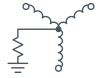
Grounding methods differ in how they respond to the first phase-to-ground fault. Solidly grounded systems allow high fault currents; low-resistance grounding limits them to lower but still substantial levels. Both require tripping, interrupting the process. Ungrounded systems can continue operating, but risk transient overvoltages and difficult fault location. High Resistance Grounding limits current so the first fault can be located and addressed without an immediate shutdown, maintaining continuity while reducing equipment stress and damage.
At a Glance

Ungrounded
Advantages
Trade-offs

Ungrounded
Advantages
Trade-offs
Low Resistance Grounded
Advantages
Trade-offs

High Resistance Grounded
Advantages
Trade-offs
Solidly grounded systems are still the default in most new low-voltage installations.
Look at the table below and ask why.
| Condition | Ungrounded | Solidly Grounded | Low Resistance | High Resistance |
|---|---|---|---|---|
| Immunity to transient overvoltages | Worst | Good | Good | Best |
| Continued production after first ground fault | Good | Worst | Worst | Best |
| Equipment protected against arc-fault damage | Worst | Worst | Better | Best |
| Safety to personnel | Worst | Better | Good | Best |
| Ground fault protection can be added easily | Worst | Good | Better | Best |
| Ability to locate a ground fault | Worst | Good | Better | Best |
| Relay co-ordination | Not possible | Good | Better | Best |
| Service reliability | Worst | Good | Better | Best |
| Maintenance cost | Worst | Good | Better | Best |
| Supports two voltage levels on the same system | Not possible | Best | Not possible | Not possible |
For a suitable system, HRG makes a compelling case for personnel safety, equipment protection and continuity. The next decision is Standard HRG or SMART HRG.
Simple math. Deliberate sizing
Inside an HRG System: The Numbers,
and What Sets Them
Consider a 480 V system protected by a 55.4 Ω neutral grounding resistor (NGR). Dividing 480 V by the square root of 3 gives approximately 277 V, which is the system’s line-to-neutral voltage.
During a ground fault, the neutral can rise to a maximum of 277 V relative to ground; it can never exceed the system’s own line-to-neutral voltage. The fault current is calculated using Ohm’s law:
| The fault-current math | Value |
|---|---|
| Neutral-to-ground voltage during the fault | 277 V |
| Neutral grounding resistor | 55.4 Ω |
| Fault current = 277 V ÷ 55.4 Ω | = 5 A |

The 55.4 Ω value is not selected to achieve a target current alone. The resulting resistor current must also exceed the system’s capacitive charging current—the current associated with its cables and windings, whether a grounding resistor is present or not. Properly sized, the resistor provides a path to dissipate stored energy and control transient overvoltages. If the resistor current is too low, the system can behave like an ungrounded system during an arcing fault, losing the transient-overvoltage control HRG is intended to provide.
The resistor limits fault current to five amps, rather than the hundreds or thousands available on a solidly grounded system. At this low current, an arcing ground fault is less likely to sustain repeated restrikes and escalate. That significantly reduces arc flash risk from a phase-to-ground fault, but does not guarantee that no arc flash can occur. See Prevention vs. Protection below for what current limitation does and does not address.
This entire calculation depends on the resistor staying intact. If it fails open, shorts, or loses connection, the system silently reverts to unprotected—fault current is no longer held to 5 A. That’s why CEC 2024, Table 17 requires continuous monitoring of the resistor’s integrity, a requirement that applies to resistance-grounded systems generally. Every I‑Gard HRG system pairs the resistor with a relay built to do exactly that; see The Relay Underneath Each System below.
Risk = Probability × Magnitude
Prevention Lowers the Odds. Protection Lowers the Impact.
NFPA 70E and CSA Z462 both recognize HRG as an arc flash mitigation technique, and for a different reason than most others on that list. Most work by reducing the energy of an arc flash once one starts. HRG is the only one that works earlier: it lowers the odds a phase-to-ground fault ever propagates into an arc flash in the first place. That’s prevention, the probability term above. Protection, acting after an arc has already started, is the magnitude term. Every I‑Gard HRG system provides current limitation. SMART HRG systems can also incorporate optional arc detection to reduce incident energy if an arc occurs.
Prevention
Lowers the odds a ground fault ever becomes an arc flash
Limiting available fault current to a few amps makes an arcing ground fault more likely to self-extinguish rather than sustain repeated restrikes and escalate. This addresses the hazard at its source, when the phase-to-ground fault first occurs.
Current limitation is the foundation of every I‑Gard HRG system.
Protection
Acts if an arc flash starts anyway
A dedicated arc detection module senses the light and pressure signature of an arc in progress and trips the breaker in milliseconds, independent of fault current magnitude. This is what limits incident energy once an arc has started.
Available as an optional arc-detection module in SMART HRG configurations or through separate arc-flash protection relays.

The next level of personnel protection
Safer Fault Location Starts with Knowing Where to Look
With Standard HRG, a technician follows the pulsing signal with a handheld meter to trace the ground fault. In a SMART HRG configuration, the relay works with a pulsing resistor and feeder sensors to identify the faulted feeder directly, allowing the search to begin downstream, where available fault current is typically lower than at the main switchgear. This more precise starting point helps personnel locate the fault more quickly and safely, adding another layer of risk reduction alongside optional arc protection.
Economics of HRG
Personnel protection is why High Resistance Grounding gets specified. The business case goes beyond safety.
What an Uncontrolled Ground Fault Does to Equipment
An uncontrolled ground fault can drive high current through motors, cables, and windings until protective equipment clears the fault. The resulting damage can be significant. One converted facility’s repair history shows the difference before and after HRG conversion.
Motor repair costs, before and after HRG conversion. One pulp and paper facility’s annual motor-repair costs associated with ground faults, shown by year. Orange bars represent the years before HRG conversion; blue bars represent the years after. The remaining costs in 2012–2014 were traced to feeders supplied by non-HRG substations at the time, rather than to an HRG system failure.
Read the source case studies →This is the experience of one facility, not a guarantee of future results. The underlying principle is straightforward: limiting fault current to a few amps instead of hundreds reduces the energy available to damage equipment. Industry data also illustrates the financial exposure. One insurer’s analysis of 156 industrial ground-fault losses over seven years reported an average loss of $769,230, including equipment damage, spoiled product, employee retraining, medical costs, and production interruption.
Estimate Your Own Exposure
One cannot put a price on personnel protection. Equipment damage and lost production time, however, have measurable financial consequences. Their cost depends on your equipment, operating costs, and fault history rather than a generic industry estimate. Enter your own figures below to estimate the cost of a single ground fault and its potential annual impact on your operation.
Four Solutions. One Clear Path.
High Resistance Grounding (HRG) is our engineering focus. Every I‑Gard HRG system limits ground-fault current, reducing arc-flash risk at its source. Sentinel and Citadel can also incorporate an optional arc-detection module to reduce incident energy if an arc flash occurs.
Personnel protection is a primary reason HRG is specified, with process continuity and equipment protection as important benefits. Every I‑Gard HRG system helps keep the process running through a first ground fault as it is being traced, while also limiting equipment damage.
The systems build on the same HRG foundation, with each offering a different level of redundancy and fault-management capability:
- Sleuth is the standard package, providing the core HRG benefits in a straightforward configuration.
- Gemini adds a second, redundant resistor path to maintain ground-fault-current limitation during service.
- Sentinel goes further by addressing a second ground fault developing on a different feeder while the first fault is still being traced.
- Citadel combines Sentinel’s second-fault capability with Gemini’s redundant resistor paths, creating an HRG architecture designed without a single point of failure.
All four systems are available in a NEMA-rated wall-mounted enclosure or as a pre-wired OEM backplate kit for switchgear integration.
Capabilities by System
| Capability | Sleuth | Gemini | Sentinel | Citadel |
|---|---|---|---|---|
| Reduces arc flash risk (limits fault current) | ✓ | ✓ | ✓ | ✓ |
| Protects against arc flash if one occurs | — | — | Optional | Optional |
| Redundant resistor path | — | ✓ | — | ✓ |
| Second ground fault isolation (SIFT) | — | — | ✓ | ✓ |

Sleuth
Production keeps running while maintenance locates and repairs the first ground fault, avoiding an immediate shutdown.
- A solution in a box: resistor and relay matched and packaged together by I‑Gard, plug-and-play from the moment it arrives.
- Limits fault current to a few amps, lowering the odds a ground fault ever becomes an arc flash, so the system doesn’t need to trip on the first fault.
- Built-in pulsing helps a technician find the fault with a handheld meter, without shutting anything down.
- The SIGMA3-C relay keeps watch on the system, and on the resistor itself.
Gemini
The same continuity as Sleuth, with a second resistor path that keeps the system protected while the other is taken out of service.
- The same solution-in-a-box as Sleuth, with twin resistor paths: if one fails, the other keeps the system running.
- Limits fault current to a few amps, lowering the odds a ground fault ever becomes an arc flash, so the system doesn’t need to trip on the first fault.
- Pulsing to find the fault with a handheld meter is available as an option, without shutting anything down.
- The SIGMA3-C relay keeps watch on the system and both resistor paths, telling a real fault apart from a resistor problem.
Sentinel
When a ground fault occurs, maintenance knows which feeder to investigate. If a second fault develops, priority-based isolation helps keep critical processes running.
- A solution in a box: resistor and relay matched and packaged together by I‑Gard, plug-and-play from the moment it arrives.
- Limits fault current to a few amps, lowering the odds a ground fault ever becomes an arc flash, so the system doesn’t need to trip on the first fault.
- Provides alarm-only operation, immediate tripping or an optional first-fault trip delay of up to 99 hours, matching the response to the facility’s maintenance policy and applicable installation requirements.
- Selective Instantaneous Feeder Trip (SIFT) isolates the lower-priority faulted feeder if a second ground fault develops on another phase, keeping the higher-priority feeder running. Supports up to 50 feeders with 16 configurable trip priorities.
- Pinpoints the faulted feeder directly, a more precise, safer starting point than tracing by hand.
- Arc Flash Detection Module (optional): trips on an arc in progress, cutting incident energy.
Citadel
The same fault-management capability as Sentinel, with a second resistor path that maintains protection while the other is taken out of service.
- SMART HRG’s DSP relay, optional arc detection module, and isolation switch, combined with twin pulsing resistor paths.
- No single point of failure on the resistor side: two resistance paths run in parallel.
- The system to specify when downtime on repair is as unacceptable as the arc flash risk itself.
One pre-wired assembly
Built Into the Switchgear
For panel and switchgear builders, all four systems are also available as a pre-wired OEM backplate kit. The resistor, relay and isolation switch are mounted and connected on one plate, without an enclosure, ready for integration into the switchgear.
The assembly is coordinated, wired and tested at the factory, simplifying installation and reducing the need to specify and connect each component separately.

Separate Resistor and Relay Locations
OHMNI is a pulsing resistor housed in its own enclosure and requires either a SIGMA3-C or DSP relay to operate. This arrangement allows the resistor to be installed near the transformer or generator, with the relay located separately in the switchgear or control room.
Sentinel and Citadel bring the resistor and relay together in a single enclosure.
The Relay Underneath Each System
Standard HRG: SIGMA3-C
Inside Sleuth & Gemini
A single, self-contained relay that combines ground fault detection with resistor-integrity monitoring. Learn more about SIGMA3-C →
Need arc protection alongside SIGMA3-C? Explore arc protection options →
SMART HRG: DSP Relay
Inside Sentinel & Citadel
A modular relay supporting up to 50 feeders. Working with a pulsing resistor and feeder sensors, it identifies the faulted feeder and provides selective isolation on a second ground fault. Learn more about DSP Relay →
Buying the resistor and the relay from two different suppliers?
The relay has to be matched to the sensing resistor, pulsing only works with the right tap/contactor, and CT/rating coordination has to span both purchases. Compliance is a property of the whole scheme, not either piece alone. See the consultant specification guide →
Typical Applications




Compliance & Standards
FAQ
Frequently Asked Questions
Answers to our most commonly asked questions. Can’t find yours? Ask here
Need Help Choosing the Right Solution?
Our engineering experts are here to help you choose the right product for your application. Whether you need technical guidance, product recommendations, or pricing, we’re ready to assist.