
Dynamic Braking Resistors
Braking Energy Has to Go Somewhere
When a variable speed drive rapidly slows a heavy load, the motor acts as a generator, feeding energy back onto the drive’s DC bus. Motor and drive losses dissipate some of that energy, but a demanding stop can generate more than they can absorb. The resulting rise in bus voltage can force a longer stopping time or trigger an overvoltage trip, interrupting the controlled stop.
When the Load Drives the Motor
Slowing a high-inertia load faster than friction turns the motor into a generator. An overhauling load does the same by supplying mechanical power to the motor, as when a hoist lowers a suspended weight. In either case, energy flows back onto the DC bus.
Without regenerative capability, the drive cannot return that energy to the supply. The bus capacitors provide limited storage, while electrical losses dissipate some energy as heat. If these are insufficient, bus voltage rises. The control system may extend the deceleration time or trip on overvoltage to protect the equipment.
For the process, that can mean a load travelling beyond its intended stopping point, an interrupted machine cycle, or production waiting while a fault is investigated and reset. With an overhauling load, the braking demand can continue throughout the movement, rather than occurring only during deceleration.
The required stopping time and operating cycle determine how much braking energy must be handled, and how quickly.
What Creates the Braking Demand?
|
Operating condition
|
Effect on braking demand
|
|---|---|
|
Rapid deceleration |
Slowing a high-inertia load quickly returns stored mechanical energy through the motor to the DC bus. |
|
Overhauling loads |
A load such as a descending hoist supplies energy to the motor, requiring braking throughout the movement, not just during stopping. |
|
Frequent stop cycles |
Repeated braking leaves less time for the resistor to cool, increasing the average heat it must dissipate. |
How a Braking Resistor Works
The motor becomes a generator
As the drive slows the load, or the load overhauls the motor, power flows backward through the inverter and charges the DC bus.
The bus voltage rises
The drive’s braking circuit watches the bus. At its turn-on level, the brake chopper switches on, connecting the resistor across the DC bus. Without sufficient energy dissipation, the drive may extend the stopping time or trip on overvoltage.
The resistor turns it into heat
The braking resistor absorbs the energy and dissipates it as heat. Its ohmic value determines how much power it can dissipate at a given bus voltage and must stay within the braking chopper’s current limits. Properly sized for the load and operating cycle, it supports faster stopping while keeping the stop under the drive’s control.
Sizing for the application
Every Stop Adds to the Thermal Load
A braking resistor converts the regenerated energy it receives into heat. Its resistance must allow sufficient braking power within the drive’s limits, while its power rating and thermal capacity must suit the operating cycle. Get the sizing wrong and the result can be a resistor that overheats, a stop that takes too long, or a braking circuit pushed past its limits.
|
Sizing parameter
|
What it determines
|
|---|---|
|
Ohms |
Determines how much current flows through the resistor and how much braking power it can dissipate at a given DC bus voltage. Lower resistance allows more current and greater power dissipation. |
|
Watts |
The continuous power the resistor can dissipate. Average braking power depends on the energy in each stop and how often stops occur; peak power and energy per stop must also stay within the resistor’s ratings. |
|
Duty cycle |
Braking time divided by total cycle time. Short braking periods can exceed the continuous power rating within specified overload limits. Long or frequent braking requires sufficient thermal capacity and cooling. |
Estimate Your Braking Resistor
Enter your drive rating and braking cycle to estimate the resistor requirements. Use the results as a starting point for sizing, not a final product selection.
Deceleration: braking torque falls as the load slows, so the average power into the resistor is about half of the peak.
Illustrative estimate based on your inputs and the calculator’s assumptions. Motor and drive losses are not deducted, which increases the estimated energy to be dissipated. Final selection must account for the resistor’s thermal and overload ratings, the actual braking threshold, and the minimum resistance and maximum braking current specified by the drive manufacturer.
I-Gard Dynamic Braking Resistors
Enclosed resistor assemblies built to your resistance and power requirements, helping prevent overvoltage trips during braking.
Five Resistor Technologies,
Matched to the Duty
Braking resistors don’t all see the same duty. Voltage, shock and vibration, overload requirements, and braking frequency vary by application. I-Gard builds each assembly using the resistor type that suits the duty, selecting the most economical style for your resistance and power requirements.
|
Type
|
Element
|
Where It Fits
|
|---|---|---|
|
CSW Smoothwound |
Stainless resistive alloy wire wound on a porcelain tube, with a refractory cement coating |
High resistance values or applications requiring an adjustable slider band |
|
FDL Wirewound |
Open helical stainless alloy wire wound around a grooved porcelain core |
Most dynamic braking applications. The open element withstands considerably higher overloads than enamel-type resistors and cools faster because every turn is exposed to ambient air. |
|
EW Edgewound |
Stainless steel strip wound on its edge and supported by grooved porcelain supports |
Applications requiring robust construction, with stainless steel terminals welded to the element |
|
SSG Stainless Steel Grid |
Stainless steel grid |
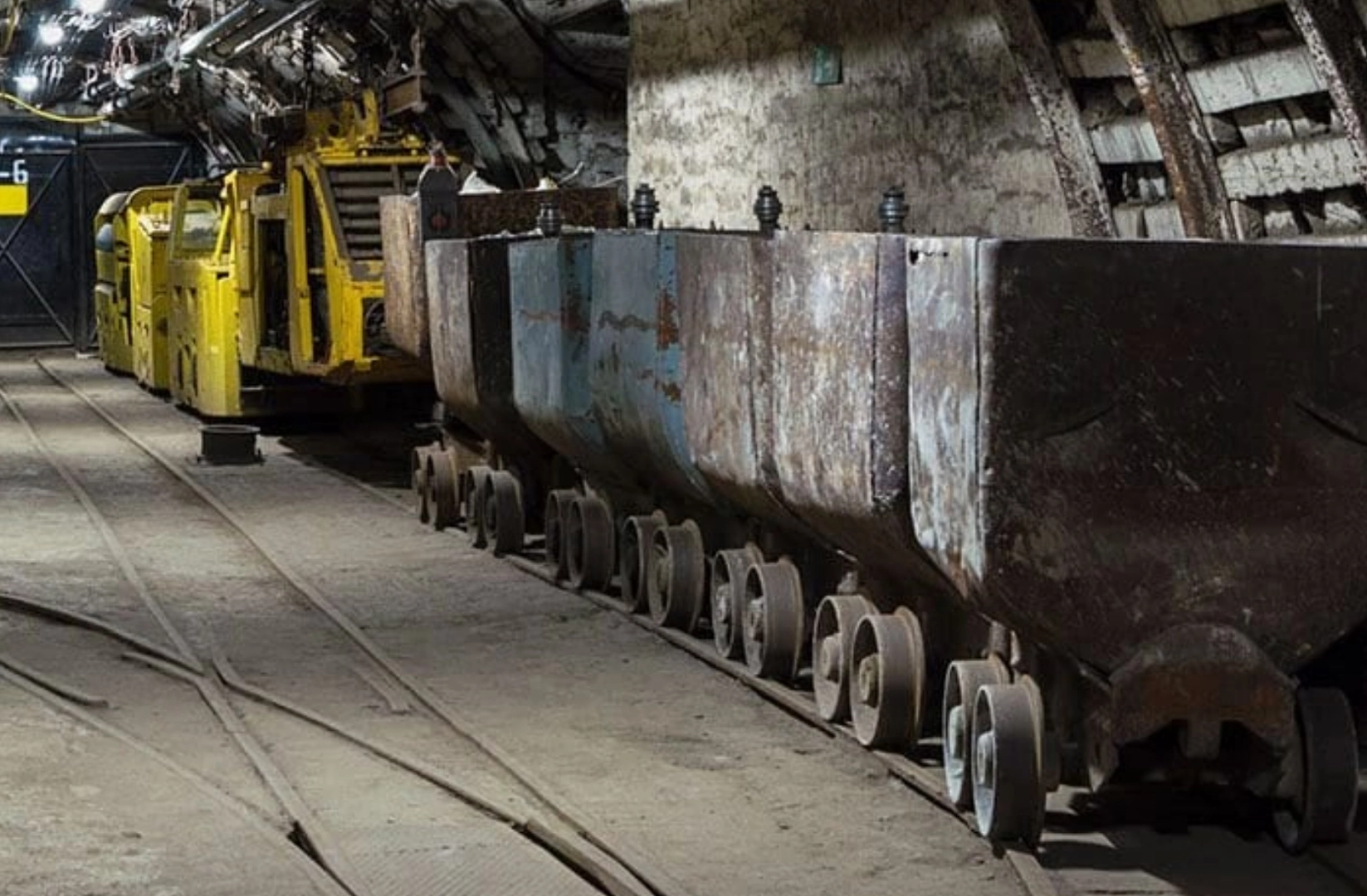
Higher wattage per bank allows fewer resistors, less space, and lower cost. Suited to the shock and vibration of overhead and tower cranes, mining equipment, and pumps. |
|
SSR Stainless Steel Ribbon |
A 4-inch-wide Type 406 stainless steel element, formed into a serpentine shape from a continuous strip nearly 30 feet long, mounted on mica-insulated through-bolts |
Large motor control and continuous duty in extreme conditions. Resistance increases by only 6% at the rated temperature rise of 375°C. Double-isolated to ground and rated at 1500 V for high-horsepower, high-voltage motors. |
Why resistance stability matters: As resistance increases with temperature, the power the resistor can dissipate at a given DC bus voltage decreases. A stable resistance helps maintain braking capability throughout a long stop.
Built for DC Duty
I-Gard builds each assembly to your resistance and power requirements, with electrical components selected for the elevated DC bus voltages encountered during braking.
Typical Applications






FAQ
Frequently Asked Questions
Answers to our most commonly asked questions. Can’t find yours? Ask here
Sizing a Braking Resistor for Your Drive?
Send us your drive voltage and horsepower, braking torque, duty cycle, load type, and the minimum ohm rating from your drive manufacturer. I-Gard will build the resistor to your ohm and wattage requirements, with standard delivery in two weeks.