
Mining Relay
Protect People from Energized
Frames on Mining Equipment
A broken ground connection and an insulation fault can leave a mining machine’s frame live, exposing anyone touching it to electric shock. The grounding loop’s condition is only part of the picture. Voltage on the machine frame itself matters to the person standing beside it.
Electrical Hazards
Don’t Announce Themselves
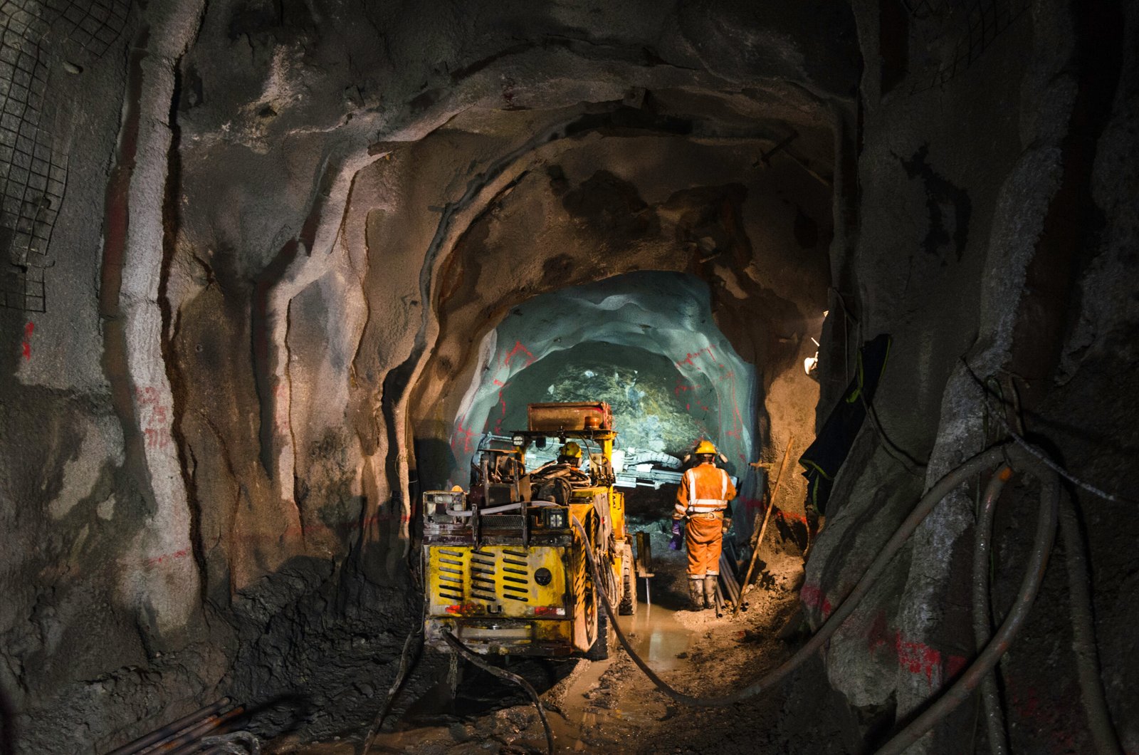
Shovels, draglines, continuous miners, drills, and portable conveyors and pumps all drag their power cables behind them. Repeated flexing and abrasion can wear a cable until the ground conductor inside breaks. If an insulation fault develops after that, the damaged grounding path can prevent the protective device from operating as intended. The machine frame can become live right where the operator stands.
Ground check monitors the integrity of that loop. It answers an essential question about the grounding connection. Frame voltage poses another: what voltage could a person encounter when touching the machine?
The operator may already have a hand on the machine when a fault develops. An energized frame creates an immediate shock hazard, making the time required to detect the condition and disconnect the supply critical to personnel protection.
When the frame is live, response time matters.
Electrical Safety
in Canadian Mines
CSA M421, Use of electricity in mines, supplements the Canadian Electrical Code with requirements for mining applications. Its scope includes mobile equipment supplied by portable power cables and addresses limiting ground-potential rise and transferred voltages to tolerable touch-voltage values in applicable installations.
For the mine, that means considering the whole path: the grounding connection, the conditions the relay detects and the breaker that removes power. Each must be selected and coordinated for the installation’s requirements.
Reference: CSA M421:23, Use of electricity in mines. Applicable requirements depend on the installation and the regulatory authority having jurisdiction.
Protection That Responds
to the Frame Voltage Itself

GCHK-100
Ground-fault, pilot-wire ground-check and frame-voltage protection for trailing-cable mining equipment.
GCHK-100 initiates a feeder trip when it detects ground-fault current that exceeds the pickup for the configured delay, a failed ground-check loop or frame voltage above the selected threshold.
The frame-voltage function reads the same pilot wire that ground check already uses. It adds protection without an extra field wire for voltage sensing, and responds faster than the ground-check function once frame voltage exceeds its setting.
Installed in the substation or power centre, GCHK-100 serves resistance-grounded applications up to 4,160 V, underground or on the surface.
What GCHK-100 Monitors
Frame-Voltage Protection
The relay monitors frame-to-ground voltage through the pilot wire and initiates a trip when the selected threshold is exceeded. Pickup settings are 40, 60, 80 or 100 V AC.
The frame-voltage detection operates within 100 ms, and within 30 ms when frame voltage exceeds 100 V AC, providing a faster response than the relay’s ground-check function.
These are relay operating times. Total clearing time also includes the connected circuit breaker or other interrupting device.
Ground Check
A monitoring current travels out along the pilot wire, through a zener terminator on the machine and back along the ground conductor. The relay initiates a trip if the loop opens, its resistance exceeds the selected setting or the terminator is shorted.
The zener terminator gives the relay a recognizable electrical signature, so a short circuit bypassing the termination can also be detected.
Ground-Fault Protection
A zero-sequence current sensor around the phase conductors measures current flowing to ground. The relay initiates a trip when the current exceeds the selected pickup for the configured delay. If the fault clears first, the timer resets.
Adjustable pickup and delay settings support coordination with the installation’s other protection.
From the Power Centre to the Machine
Relay at the Power Centre
GCHK-100 connects the monitoring inputs to the feeder’s trip circuit. Local indicators show ground-check, ground-fault and frame-voltage status, giving personnel a starting point when investigating a trip.
Current Sensor at the Feeder
I‑Gard T-series sensors are available in different window sizes to suit the conductors.
Pilot Wire and Terminator at the Machine
The standard GCHK-ZT terminator is installed at the machine.
The relay version and terminator must be matched. The standard GCHK-100 uses a nominal 6 V termination; GCHK-100-Z12V supports a 12 V termination.
Status Where Personnel Need It
The optional GCHK-DRI brings the relay’s status lights and reset/test controls to a panel or other accessible location.
For several feeders, the optional mGARD-SYM brings up to 50 relays onto one display. Personnel can select a relay, view its status and settings, and see measurements as a percentage of the selected trip level. Remote reset/test and an isolated Modbus RTU interface support operation and supervisory integration.
Replacing an Existing Ground-Check Relay?
GCHK-100 supports I‑Gard and compatible third-party current sensors, offering a practical retrofit option for adding frame-voltage protection. That flexibility can allow suitable components to remain in service. I‑Gard can review your existing sensor, pilot-wire termination, wiring, mounting, control power and trip arrangement to confirm what can stay and what needs to change.
FAQ
Frequently Asked Questions
Answers to our most commonly asked questions. Can’t find yours? Ask here
Protecting Mobile Mining Equipment?
Send I‑Gard your resistor monitoring requirements. Our engineering team can help confirm the SIGMA3-C configuration, sensing components, and display options for your equipment.